1. INTRODUCTION
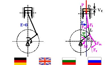
In the classic scheme as a base for construction of an internal combustion engine are the axis of cylinder and the axis of crankshaft on the same plane and perpendicular each other. I’ll show here the findings of the theoretical study of the internal combustion engine main features, which axis of cylinder and axis of crankshaft are not on a same plane and the axis of cylinder is parallely removed at distance E from its traditional position on the crank rotation plane of the crankshaft, i.e. they are crossed (figure above the heading).We’ll call the distance E eccentricity.
The studied parameters as a function of the eccentricity are in 2 groups: energy – the indicator work (correlating with the indicator power) and the torque, and power – forces applied on the crank-rod mechanism and the piston-cylinder group. Together with the torque we’ll calculate its mean square deviation σ. It gives an idea of the crankshaft rotation steady.
The indicator work is

Pv is the pressure in the cylinder as a function of the cylinder volume V.
The mean torque is

(2),
Mφ is the running meaning of the torque as a function of the angle φ, n = 2 or 4 (engine strokes 2/4).
Forces applied on the crank-rod mechanism and the piston-cylinder group are expressed through trigonometric equations. Their average value is determined through integral solving like (2).
During studying of the internal combustion engine dimensions as a function of the eccentricity is to recognize – the maximum cylinder chamber volume (Vmax) in the both ends of the definition area grows up to a value which grows up with the increasing of rod length:
(3),
VC is the volume of the combustible chamber, S is the piston stroke, D is the cylinder diameter, L is the rod length, E is the eccentricity of the cylinder axis, R is the crank length. The definition dimension area of that internal combustion engine kind is L>R and |E|<L-R.
2. MATHEMATICAL STUDY MODEL FOR THE PARAMETERS IN A REAL INTERNAL COMBUSTION ENGINE THROUGH ITS PV DIAGRAM TREATMENT

The here realized mathematical model for calculating of pressure in the cylinder chamber with various values of the eccentricity E is based on a turned out real PV diagram for an existing internal combustion engine, built according to a classic scheme (E=0) with a determined condition – supplied fuel and applied load. As a function of eccentricity are determined the analyzed energy features and forces with kept constant cylinder chamber volume (with kept constant real compression level ε) and supplied fuel. The PV diagrams, served as a base model, are taken through MIP Calculator (Combustion Analyzer), used in Bulgarian Navigation Maritime too.
3. FUNCTIONAL DEPENDENCES OF MAIN FEATURES FROM THE ECCENTRICITY
Here are showed mathematical model diagrams for several internal combustion engines functionally related depending of the rated eccentricity e=E/R: indicator work Aind, mean torque Mav, mean square deviation of torque σ and average values of forces, applied upon: piston pin Fb, rod and rod’s bearing Fl, couple piston-cylinder Fn, perpendicular to the crank in the crank pin bearing Fm and the main bearing Fr. All diagrams are built with their rated values (in %), i.e. divided by their values with zero eccentricity (Е=0); the diagrams with index a are on characteristic places on the abscissa with increased scale and decreased step; the force Fn is showed through its absolute value |Fn| and through its components – the positive +Fn and the negative |-Fn|.
3.1. Internal combustion engine 6ДКРН 67/170-4, Machine-building plant Briansk, Russia, main engine of motor ship Stanko Staikov (internal combustion engine prototype B&W K67GF) – diesel, 2 strokes

3.1.1. Diagram of rated dependences of indicator work Aind, mean torque Mav, mean square deviation σ.

3.1.1.a. Diagram of rated dependences of indicator work Aind, mean torque Mav, and mean square deviation σ – with decreased step on the eccentricity and increased scale on the ordinate.

3.1.2. Diagram of rated dependences of forces: Fr, Fl и Fm - average values.

3.1.3. Diagram of rated dependences of forces |Fn| and its components +Fn и |-Fn| - average values.

3.1.3.a. Diagram of rated dependences of forces |Fn| and its components +Fn und |-Fn| - average values with decreased step on the eccentricity and increased scale on the ordinate.
3.2. Internal combustion engine MAN-B&W 4S26MC, main engine of motor ship POLLUX – diesel, 2 strokes

3.2.1. Diagram of rated dependences of indicator work Aind, mean torque Mav, mean square deviation σ.

3.2.1.a. Diagram of rated dependences of indicator work Aind, mean torque Mav, and mean square deviation σ – with decreased step on the eccentricity and increased scale on the ordinate.

3.2.2. Diagram of rated dependences of forces: Fr, Fl и Fm - average values.

3.2.3. Diagram of rated dependences of forces |Fn| and its components +Fn и |-Fn| - average values.

3.2.3.a. Diagram of rated dependences of forces |Fn| and its components +Fn und |-Fn| - average values with decreased step on the eccentricity and increased scale on the ordinate.
3.3. Internal combustion engine SULZER 5AL25/30, diesel-generator No 1 of motor ship ROZHEN – diesel,4 strokes

3.3.1. Diagram of rated dependences of indicator work Aind, mean torque Mav, mean square deviation σ.

3.3.1.a. Diagram of rated dependences of indicator work Aind, mean torque Mav, and mean square deviation σ – with decreased step on the eccentricity and increased scale on the ordinate.

3.3.2. Diagram of rated dependences of forces: Fr, Fl и Fm - average values.

3.3.3. Diagram of rated dependences of forces |Fn| and its components +Fn и |-Fn| - average values.

3.3.3.a. Diagram of rated dependences of forces |Fn| and its components +Fn und |-Fn| - average values with decreased step on the eccentricity and increased scale on the ordinate.
3.4. Internal combustion engine SULZER 8BAH22, diesel-generator No 3 of motor ship BELMEKEN – diesel, 4 strokes.

3.4.1. Diagram of rated dependences of indicator work Aind, mean torque Mav, mean square deviation σ.

3.4.1.a. Diagram of rated dependences of indicator work Aind, mean torque Mav, and mean square deviation σ – with decreased step on the eccentricity and increased scale on the ordinate.

3.4.2. Diagram of rated dependences of forces: Fr, Fl и Fm - average values.

3.4.3. Diagram of rated dependences of forces |Fn| and its components +Fn и |-Fn| - average values.

3.4.3.a. Diagram of rated dependences of forces |Fn| and its components +Fn und |-Fn| - average values with decreased step on the eccentricity and increased scale on the ordinate.
4. ANALISIS OF FUNCTIONAL DEPENDENCES AS RESULT OF ECCENTRICITY
The analysis of the functional dependences of energy features and acting forces show:
4.1. In case of 2 strokes engines, the work increasing together with increasing of eccentricity in positive direction and decreasing in case of eccentricity in negative direction; in case of еmax the work increasing till to 108%-125%, in case of е ≈ 1 the work increasing till to 120%. In case of 4 strokes engines the curve of work looks like upturned parabola, i.e. the work is decreasing; in the beginning in negative direction the work is near to 100%, but after that it falls faster till to lower values; at еmax the work ca fall till to 70%-85%.
4.2. The curves of mean torque are a broken line, fluctuating around a line, following the curve of work changes. In case of 2 strokes engines with еmax the mean torque reaches to 105%-130%, with е ≈ 1 have the max values are between 105%-125%. In case of 4 strokes engines there are only particular peaks over 100%; but that peaks are around 101%-102%.
4.3. The mean square deviation curve of the torque has a upturned parabola nature, i.e. with increasing of eccentricity is the steady of crankshaft rotation increasing. In case of 2 strokes engine when eccentricity is near to maximum, the mean square deviation decreases 15% till to 30%, when eccentricity value е ≈ 1 the mean square deviation decreases 3% till to 10%. In case of 4 strokes engine the parabola maximum become at e = [-0.9,-1.4] and is about 101%-102%, i.e. the rotation steady is getting worse; by larger eccentricity in negative direction the mean square deviation falls promptly, but till to the higher values than values by eccentricity in positive direction.
4.4. The functional dependences of the average values of forces Fr and Fl are deviated slightly from 100%. In case of 2 strokes engines the deviation in direction decreasing of their main values; in case of 4 strokes engines the force Fr decreases too, but the force Fl increases. Fm follows the change of the mean torque.
4.5. The curve of force |Fn| has a parabola nature with minimum 80%-95% in interval e = [0.1,0.4]. With maximum allowable eccentricity values the increase of that force can reach till to 15-20 times. When eccentricity value is about е ≈ 1 is the increase of the mean value is in the frame of 5 till to 15 times. If the eccentricity is more than 0,6-0,7 only one force component is different than zero, i.e. loaded is only one side of couple piston-cylinder.
5. CONCLUSION
In cases of 2 strokes internal combustion engines with positive eccentricity applied, indicator work can be increased, i.e. can be increased the power of engine and substantially of the mean torque with a visible increasing of crankshaft rotation steady. All this is realized without any changes of supplied fuel. It cause increasing of engine efficiency and decreasing the fuel consumption. That means, the economic indexes of the internal combustion engine and of the complete system will be improved. In cases of 4 strokes internal combustion engines increasing of indicator work can't be reached, but some increasing of the mean torquecan be noticed.
At the same time, decreasing of friction losses in the couple piston-cylinder and their wear down can be achieve when eccentricity is in the zone of force minimum |Fn|. To construct an engine with eccentricity in order to increase indicator work and mean torque, decreasing fuel consumption, is only reasonable if the decreasing of friction losses can be achieve by means of additional constructional and technical measures. Good example are existing 2 strokes crosshead engines.
—————————————————————————————————
Published in magazine “Machinery building and Electrical engineering” No 5/2005, Scientific and Technological Union, Bulgaria. Presented at the 12th International Scientific and Technological Conference “TRANS & MOTAUTO ‘05”, 2005, City of Veliko Tarnovo, Bulgaria.
Няма коментари:
Публикуване на коментар